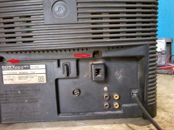
SONY Trinitron KVG14Q2 Repair Help FROM MY SERVICE TABLE TODAY
- Get link
- X
- Other Apps
TDA8374A (Chroma)_STR S6707 (SMPS switching)_LA7830 (Vertical Scan Output IC)_ Sharp PQ 09RE 11 (9V controlled voltage regulator IC) _ 2SD1877 (Horizontal Scan Output Transistor)_NX1733/m (FBT/LOT)
 |
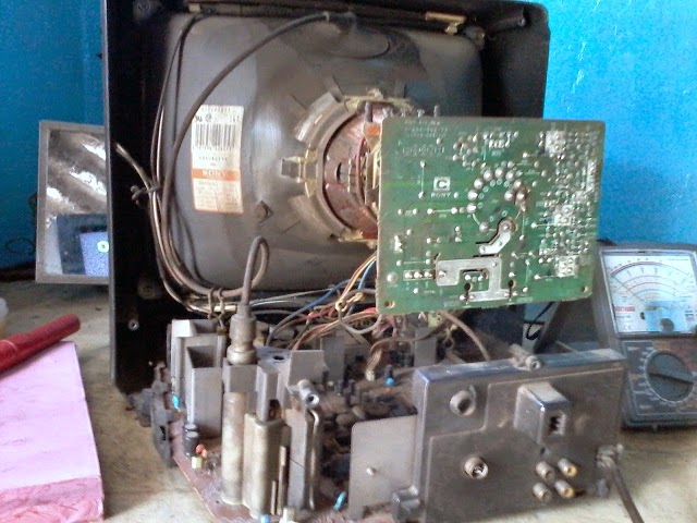
Set received for repair with no picture condition; today.
On power ON, the standby LED blinks 3 times and then shuts off.
As the standby LED blinks, at least once time, it is clear that the SMPS section circuit to this set is working properly.
But, the main system control mcro-computer IC detects something short circuit with any component/s at the main board.
As the set is a very old model, the spare part availability will be somewhat difficult. So; I should take much care with work; not to damage more components.
I opened the back cover. A visual inspection is done for any damaged component/s on-board. Such as bulged/shorted capacitors, damaged IC/s and such.


I found that the vertical scan output IC is cracked. I’ve attached the photo of the same here.

Checked all other main components, which can likely to be faulty; using multi-meter. Checked the Horizontal Output Transistor for any leak with its junction The Horizontal Output Transistor used with this set is D1877. I did notice, it is the original one fitted by the company. Nobody have replaced it. We can detect this by inspecting its solder terminals.
Yet, de-soldered it out from the circuit board, and checked it alone using meter set to KOhms range. No abnormal measurement noticed. De-soldered it into place again. Screwed it on to its heat sink.
De-soldered out the damaged vertical scan output IC from the circuit board.
Switched ON the set without it.
The standby LED lighted up once, then 3 times and OFF, as before.
[With this set’s circuit, it won’t switch ON properly, or produce EHT or even a horizontal line will appear on the screen, as other company’s sets will; except the +B voltage [112VDC] only will be present.
I did check the +B112VDC. It was OK. No fluctuations. Checked the voltage at the primary winding of the line drive transformer, and at the collector terminals of the Line Drive Transistor. All found OK.
Switched OFF the set, and checked all the solder terminals at the solder side of the PWB, once more; using a magnifying glass.
After some time, at about 25 minutes, I detected a minute loose solder terminal at the 9V voltage regulator IC. This IC has 4 solder terminals. It is a controlled voltage regulator, which in turn controlled by the main microcomputer IC. If the microcomputer IC detect any short circuit anywhere at the circuit board, it will shut down the control voltage to this IC; and it will down the 9VDC, which goes to the main chroma oscillator jungle IC [TDA8374A], and that was happening here.
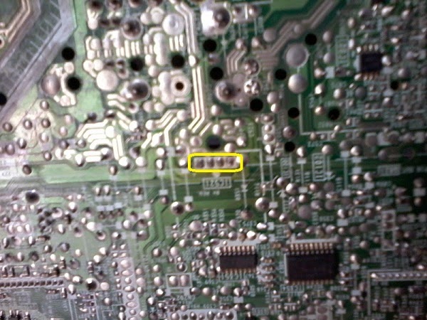

But here there were two faults. The loose solder terminal at the regulator IC said above (IC521 Pin-1). The vertical scan output IC (LA7830) short.
Re-checked all the solder terminals at the main board to make sure that there are no other loose solder terminals.
Set switched on; fed to RF signal [On-Air]. Tuned it. OK.

| 1 |  | 1 |  |
FBT BSC26-N2138 D16 110V
Switching transformer EER4942 300UH
Linearity Coil HL-1520S-26.5uH 26.5uH 50V 4A
ICs used STV9326_LF353N_C6090_STR-X6556_STR-A6151

SMPS SCHEMATIC

DEFLECTION

SYSCON-CHROMA

CLICK ON THE SCHEMATICS TO ZOOM IN
Samsung Plano CZ21K 30G1 Flat TV - TDA9381 (System control_Chroma_Oscillator Jungle IC)

Set got for repair in dead condition today.
The owner said that its LOT is damaged, as somebody told him so; during a home call repair attempt. As I asked some more details, I did understand that the owner is professionally a Doctor. He knows only what the service technician said to him. That’ll be so. Because all doctors might not be aware in electronics.
Suppose that, I’m before him with any physical disorder. What can I do is just to follow his advice; take the medicines he prescribes and do what else he advice. Because, I’m not aware in medicine.
Like ways is here. The TV technician told him that the LOT is damaged; and the doctor recited it to me. That’s all.
Whatsoever it may be. Let me go with my work.
I did open the back cover of the set. There were only two seating screws at the top. The two others at the bottom is lost.
As somebody has already worked with the TV, I should be careful before plug it into AC power.
I pulled out the PWB, and checked all its print side to know whether anybody have worked with it; or not.
No solder work done.
Yet; I've double checked to make sure about it.
After confirming that no work has done with the PWB, I plugged it to AC mains, and switched it ON.
The standby/power LED at the front panel lighted up, stayed for about 2 seconds, and gone OFF.
Yes. Clear evidence that its SMPS power regulator section circuit is working fine. One major check-point is over.
Checked the +B(110VDC) at the cathode of D605.
Found OK. It shows +111.2VDC
Here one thing I’ve to specify is the worst printing quality of Samsung. They have printed all the component numbers with black ink and the PWB is masked with green lacquer. We can’t note the part number without taking some strain to eyes. If it were printed in white color, might be great.
Here the 110VDC supply line is OK.
There are two other important voltages too should be. The 12VDC & 8VDC.
12VDC is used to the horizontal drive stage and the 8VDC used to supply the main system chroma IC TDA9381.
I've noted that the heat-sink to the STR at the SMPS stage heats up slightly. It is normal, as that stage works properly.
Measured the voltage at the collector terminal of the Horizontal Drive transistor.

Found abnormal. It showed only (0.87VDC). It should be around 11.3VDC normally.
With this set, an IC is used as DC voltage regulator to derive 12VDC & 8VDC. [IC802 – KA7632]; a controlled dual voltage output IC.
Checked the input voltage to this IC at its pins 1&2. It was OK. At about 14.5VDC – from the SMPS.
Further checking revealed that the solder terminals to this IC (10 pins) appeared somewhat bad. As this IC will heat up somewhat 40 degrees centigrade, during normal working, the solder terminals to it too will heat up to that temperature. Repeated heating and cooling can make the solder terminals to expand and to shrink, and thus (Dry-solder) joints can be.
I've de-soldered out all the solder from these 10 terminals, and re-soldered by applying fresh solder to all.


Plugged the set to AC mains, and switched it ON
OK. The raster appeared
Here I've to do some more work with this set. Its focus is out. Somebody might have touched the focus and screen voltage pot-meters at the LOT.
Entered the Service Mode to Samsung and adjusted all the data parameters as specified in the service manual. Adjusted the Focus to get picture at maximum clarity. That’s all.
It took around 3 hours to finish this work. It isn’t a matter. Some work may be easy; the others will be time taking.
Voltages at the terminals of horizontal drive transistor.
Collector > 12.29V
Base > 0.531V
Emitter > Ground.


To check the reset circuit, the reset output is low to discharge the delay capacitor (=Cd). If it’s less than Vo1-0.25V. And the reset output is high when the delay capacitor voltage linearly increased by the internal current source(10µA) if it’s more than Vo1- 0.2V. The equations of delay time are same as below. Trd = (Cd × 2.5) / 10µA. These parameters, although guaranteed, are not 100% tested in production.
The KA7632/KA7633 [ FAIRCHILD] is a multi-output positive voltage regulator designed to provide fixed precision output voltages of 3.3V, 8V (KA7632) / 9V (KA7633) at current up to 0.5A and 5.1V at current up to 1A with external PNP transistor. An internal reset circuit generates a reset pulse when the output 1 decrease below the regulated value. Output2 & 3 can be disabled by TTL input. Protection features include over voltage protection, short circuit protection and thermal shutdown.
> Output Currents up to 0.5A (output1 & 2)
> Output Current up to 1A with External Transistor (output3)
> Fixed Precision Output 1 voltage 3.3V ± 2%
> Fixed Precision Output 2 voltage 8V ± 2% (KA7632)
> Fixed Precision Output 2 voltage 9V ± 2% (KA7633)
> Control Signal Generator for Output 3 voltage (5.1V ± 2%)
> Reset Facility for Output Voltage1
> Output 2,3 with Disable by TTL Input • Current Limit Protection at Each Output
> Thermal Shut Down.
To check the reset circuit, the reset output is low to discharge the delay capacitor (=Cd). If it’s less than Vo1-0.25V. And the reset output is high when the delay capacitor voltage linearly increased by the internal current source(10µA) if it’s more than Vo1- 0.2V. The equations of delay time are same as below. Trd = (Cd × 2.5) / 10µA. These parameters, although guaranteed, are not 100% tested in production.
| 0 | | 0 | |
SMPS _ Power Amplifier Circuit Diagram and General Troubleshooting _ harman kardon HS200 Home Cinema System [STA508_FAN7528MX_FAN7602_KTC8550 (FET)]

Power requirements: AC 230 V, 50 Hz
Max power consumption: 300 W
Idle power consumption: Less than 2 W
Dimensions (WxHxD): 350mm x 84mm x 250mm
Weight: 3.8 kg
If you experience any of the following difficulties while using the system, use this troubleshooting guide to help you remedy the problem. Should any problem persist, consult your authorized Harman Kardon dealer.
No power.
* Is the power cord firmly plugged into the power outlet?
* One of the safety mechanisms may be operating. In this event, unplug the player from the power outlet briefly and then plug it in again.
* Is the power cord firmly plugged into the power outlet?
* One of the safety mechanisms may be operating. In this event, unplug the player from the power outlet briefly and then plug it in again.
No picture.
* Check that the system is connected correctly and securely.
* The video cable may be damaged. Replace it with a new one.
* Make sure the system is connected to a video input on the TV.
* Make sure the TV is turned on.
* Make sure the correct video input on the TV is selected for viewing with this system.
Noise (interference) appears in the picture.
* Clean the disc.
* If video from this system has to go through your VCR to get to your TV, the copy-protection applied to some DVD programs could affect picture quality. If you still experience problems after checking your connections, please try connecting your DVD system directly to your TV’s S-Video input, if your TV is equipped with this input.
The aspect ratio of the screen is wrong (picture vertically expanded) when you play a wide picture even though you set “TV DISPLAY” in the SETUP menu to "16:9".
* If you connect the system with the SCART cable, connect directly to the TV. Otherwise the auto-switch function of the aspect ratio for the TV may not work.
* If the TV is not connected with a SCART cable to the HS, or if the auto-switch function does not work you should turn the TV to "16:9" (if possible with your TV).
* Depending on the TV, you may not be able to change the aspect ratio. In that case (TV not adjustable to 16:9) do not select "16:9" in the TV Display. Then, no change of the aspect ratio is needed.
There is no sound or volume is very low.
> Check that the speakers and components are connected correctly and securely.
> Make sure that you have selected the correct source on the system.
> Press MUTE on the remote control, if the words MUTE ON are blinking on the front panel display.
> The protective circuitry has been activated because of a short circuit. Turn off the system, eliminate the short circuit problem and turn on the power again.
> The audio interconnect is damaged. Replace it with a new one.
> The system is in pause mode or in slow-motion play mode, or fast forward or fast reverse. Press ( > ) to return to normal play mode.
The left and right channels are unbalanced or reversed.
* Check that the speakers and components are connected correctly and securely.
Severe hum or noise is heard.
* Check that the speakers and components are connected securely.
* Check that the connecting cords are away from a transformer or motor and at least 3 meters away from fluorescent light.
* Move your TV away from the audio components.
* The plugs and jacks are dirty. Wipe them with a cloth slightly moistened with alcohol.
* Clean the disc.
The volume goes down automatically and cannot be increased.
The internal temperature is too high. Wait approximately one minute for the amplifier to reach normal working temperature.
The internal temperature is too high. Wait approximately one minute for the amplifier to reach normal working temperature.
Radio stations cannot be tuned in.
* Check that the antenna is connected correctly. Adjust the antenna and connect an external antenna if necessary.
* The signal strength of the stations is too weak for automatic tuning. Use manual tuning.
* No stations have been preset.
* The tuner mode is not selected, select the Radio mode.
* Check that the antenna is connected correctly. Adjust the antenna and connect an external antenna if necessary.
* The signal strength of the stations is too weak for automatic tuning. Use manual tuning.
* No stations have been preset.
* The tuner mode is not selected, select the Radio mode.
The remote does not function.
> Remove any obstacles between the remote control and the system.
> Move the remote control closer to the system.
> Point the remote control at the remote sensor on the front panel.
> Replace all the batteries in the remote control with new ones if they are weak.
> Check that the batteries are loaded correctly.
The disc does not play.
* There is no disc inside. (“NO DISC” appears on the front panel display and the TV screen.) * Insert a disc.
* Insert the disc correctly with the playback side facing down on the disc tray.
Clean the disc.
* There is no disc inside. (“NO DISC” appears on the front panel display and the TV screen.) * Insert a disc.
* Insert the disc correctly with the playback side facing down on the disc tray.
Clean the disc.
* DVD with wrong region code.
The system starts playing the DVD automatically.
The DVD features the auto playback function.
The DVD features the auto playback function.
Playback stops automatically.
Some discs include an auto pause signal. When playing such a disc, the system stops playback at the signal.
Some discs include an auto pause signal. When playing such a disc, the system stops playback at the signal.
Track Skip or direct select with numeric buttons, Search, Slow-motion play, repeat play or Program play, etc., cannot be done.
Depending on the DVD or VCD, some of the above operations may not be available.
Depending on the DVD or VCD, some of the above operations may not be available.
Messages do not appear on the TV screen in the language you want.
Select the language for Display and Preferred Subtitle in the SETUP menu. For all messages from the DVD (DVD menu, subtitles) in the proper language the disc must have the language you selected, if not, another language will be selected.
Select the language for Display and Preferred Subtitle in the SETUP menu. For all messages from the DVD (DVD menu, subtitles) in the proper language the disc must have the language you selected, if not, another language will be selected.
The audio language cannot be changed when you play a DVD.
* Multilingual sound is not recorded on the DVD.
* Changing the language for the sound by the Audio button on the remote or the Audio line in the Player Menu is prohibited on the DVD. In that case the audio language must be selected by the main menu on the DVD.
* Multilingual sound is not recorded on the DVD.
* Changing the language for the sound by the Audio button on the remote or the Audio line in the Player Menu is prohibited on the DVD. In that case the audio language must be selected by the main menu on the DVD.
The subtitle language cannot be changed when you play a DVD.
> Multilingual subtitles are not recorded on the DVD.
> Changing the language for the subtitles by the Subtitle button on the remote or the Subtitle line in the Player Menu is prohibited on the DVD. In that case the subtitle language must be selected by the main menu on the DVD.
> Multilingual subtitles are not recorded on the DVD.
> Changing the language for the subtitles by the Subtitle button on the remote or the Subtitle line in the Player Menu is prohibited on the DVD. In that case the subtitle language must be selected by the main menu on the DVD.
The subtitles cannot be turned off when you play a DVD.
Depending on the DVD, you may not be able to turn the subtitles off.
Depending on the DVD, you may not be able to turn the subtitles off.
The angles cannot be changed when you play a DVD.
* Multi-angles are not recorded on most DVDs.
* Change the angles when the angle mark appears on the TV screen.
* Changing the angles is prohibited on some DVDs.
* Multi-angles are not recorded on most DVDs.
* Change the angles when the angle mark appears on the TV screen.
* Changing the angles is prohibited on some DVDs.
The system does not operate properly.
Static electricity, etc., may affect the system’s operation. Disconnect the AC power cord, and then connect it again.
Static electricity, etc., may affect the system’s operation. Disconnect the AC power cord, and then connect it again.
POWER AMPLIFIER SECTION CIRCUIT

SMPS CIRCUIT


CLICK ON THE PICTURES TO ZOOM IN
The set got for repair in dead condition. Set has stopped working after a lightning, the party said.
Click on the pictures to Zoom In.
Click on the pictures to Zoom In.

I opened the back cover. Checked the components at the SMPS [power supply regulator] board, as it might be most hit by lightning. The 5Amp glass cartridge type fuse found burned and broken to pieces.

Some other damaged component/s will be there. It’s sure.
I did measure the voltage across the main filter capacitor [C628] 120MFD 450VDC; to check whether there is any residual static charge retains; because, if there is any voltage, my multi-meter will get damaged, when I try to measure the DC resistance across it. If there is any static voltage, we must fully discharge it before we measure resistance across its terminals.
No such static voltages detected.
I set the multi-meter to measure Ohms, and did measure the resistance across the main filter capacitor, mentioned above. I've attached photo of the SMPS board here.

The result was abnormal. Measured only less than one Ohms. There is a short circuit, at the mains rectifier section circuit itself.
Un-screwed out the SMPS board, to check which component/s are shorted / damaged.
(In this condition, the only way to check is by de-solder out the suspected component/s from the circuit board, and check it.]
I de-soldered out the mains rectifier stalk [marked here the position of it at the SMPS board]; and checked its DC resistance. It revealed that it has shorted junction inside; measuring a DC resistance less than 1 Ohms between its (+ve and (–ve) terminals. It has been damaged. A voltage spike caused by lightning has damaged it; dead short, causing the AC mains protection fuse to break into pieces.

Now it is sure that there will more damaged components. Without the rectifier stalk on board, I did measure the DC resistance across the mains filter capacitor; mentioned above. No short circuit detected now.
Checked the mains filter capacitor out from the circuit for it capacitance; using capacitance meter. It was OK. Measured 132MFD. Yet, it will be best to replace it with a new one, because it has already been hit by a high voltage spike. Even if it will work right now, might cause trouble with time.
Replaced the main rectifier stalk, and the mains filter capacitor. Double checked the circuit and made sure that there is no more short circuit.
Plugged the set to AC mains wall socket, and switched it ON.
I didn't heard any ‘relay click’ as this model sets will produce normally during power ON.
Checked the DC voltage across the mains filter capacitor again, and found normal as it should be.
On further checking, one among the three opto-couplers used was damaged {part number marked on board is PC803 (PC123)]. Its LED side open.

Replaced both the opto-couplers PC803 & PC801. Both are of same number (PC123).
Now switched on the set. OK.
There was no other fault with its main board. If were, I might have to return the set, as main board to this set is not available at local electronic spare part marked here.
THE ORIGINAL REMOTE CONTROL NUMBER TO THIS SET IS
N2QAYB 000399

Universal remote control set-up codes to Panasonic are:
0016 0032 0033 0049 0054 0075 0099 0101 0104 0107 0110 0119 0143 0151 0152 0161 0166 0207 0249 0304 0305 0306 0396 0420 0461 0611 0631 0633 0692
| 0 | | 0 | |
The DVD player will start-up at first, No Display, and will shut down immediately. A "Tik-Tik-Tik" noise will be produced continuously from the SMPS board. No response to any key buttons on the panel or with the remote control.
CLICK ON THE PICTURES TO MAGNIFY
Checked the DC voltage across the main filter capacitor. Found normal.CLICK ON THE PICTURES TO MAGNIFY
Checked all the other components on SMPS board. All the SMD transistors used is OK. Checked all the diodes. OK. Checked the opto-coupler . OK.
On through checking, the D212 {Zener Diode} was found leaky.
This diode can be located near to the capacitor C511 [I've marked it here]
Switching STR used is > MIP2E4D. Opto-coupler > PC817.


Note the type of fuse [F101] used with this SMPS. It is rated at 1.25Amps 250VAC. We can use any type of fuse in place, provided it should be of the same rating. No other restrictions.
LEAKAGE CURRENT HOT TEST

> Plug the AC cord directly into the AC outlet. Do not use an isolation transformer for this check.
> Connect a 1.5kΩ, 10 watts resistor, in parallel with 0.15µF capacitors, between each exposed metallic part on the set and a good earth ground such as water pipe, as shown here.
> Use an AC voltmeter, with 1000 ohms/volt or more sensitivity, to measure the potential across the resistor.
> Check each exposed metallic part, and measure the voltage at each point.
> Reverse the AC plug in the AC outlet and repeat each of the above measurements.
The potential at any point should not exceed 0.75 volts RMS. A leakage current tester (Simpson Model 229 or equivalent) may be used to make the hot checks, leakage current must not exceed 1/2 milliamp. In case a measurement is outside of the limits specified, there is a possibility of a shock hazard, and the equipment should be repaired and rechecked before it is returned to the customer.
The set received for repair in dead condition. There was no Model number or any other details, nowhere on the set or its inside.
The power LED at its front panel lights up; upon switch it ON, and goes ‘dim’ immediately and shows fluctuations in its intensity.
An “Ish, Ish, Ish” noise is heard form the SMPS side circuit of the set.
No audio thumb, no video or filament of the CRT do not glow.
Checked the voltages out from the SMPS.
All the output voltages were OK; except +B111VDC. It measured at about 81VDC, and is fluctuating.
The Horizontal scan output transistor overheats too.
Clear evidence to damaged LOT [Line Output Transformer].
De-soldered out the horizontal output transistor, and checked it with multi-meter set to Meg-Ohms range.
No abnormal measurements detected.
Un-soldered out the LOT.
There was no number sticker on it.
Without its number, it will be difficult to get from the electronic spare part market.
I called the party, and asked them to buy it from anywhere.
He has bought one.
The number of the new LOT he bought is [TF-0107-OU BSC 24-01-40] Might be a Chinese make.
Not sure; whether it is the original number or not. I’ve attached the photo of both the LOTs here.
CLICK ON THE PICTURES TO ZOOM IN


Replaced the LOT and HOT [Line Output Transformer & Horizontal Output Transistor]
Checked all the other components by following its schematic. The main board to this TV is shown here. As there is no model number, that I can see anywhere in the set, I did follow a schematic using the main system control chroma jungle IC TDA9370PS; as in this main board too used the same.
No other problems detected.
Connected to AC mains; and switched it ON.
There is no raster at all; but the CRT filament is glowing.
Checked the +B voltage; once again. OK. 111.5VDC.
As the LOT is a new one, the screen volt pot-meter of it was set to extreme left [Minimum].
Advanced the pot-meter, till the raster came up.
Kept it at this condition for about 10 minutes.
Switched it OFF; unplugged it from AC mains socket, touched the heat sinks of both SMPS drive transistor and the Horizontal Scan Output transistor.
The heat at HOT heat-sink was normal; but it was abnormal at SMPS drive transistor.
A slight overheat felt to my fingers. At the same time, when I switched it ON; a very feeble high-frequency noise was there coming from the SMPS transformer. It shouldn't be so. Must be so silent. I did suspected the windings inside this transformer for a while, but it was not.
When I touched the +B voltage smoothing capacitor, 100MFD160VDC, it was too hot. It shouldn't be so. Must be cool.
I de-soldered it out from the circuit board, and tested it for capacitance. Shows only 30MFD. Checked its electrolyte leakage resistance. Shows only 135Ohms. This capacitor is damaged. We can say it to be leaky. Just see, there was no bulging on this capacitor; yet it is damaged.
Replaced the capacitor with a new one of same capacitance.
Switched ON the set, and tuned in to an on-air program; after connecting it to external antenna.
Auto-tune function is OK. Tuning memory lock is OK.
But; some color patches are at the screen.
Replaced the de-gassing posistor; as it might be the possible reason. Yes. It was.
Checked the set. OK.
MAIN BOARD

THE COMPONENTS I DID REPLACE

PICTURE - AFTER REPAIR

The party has lost its original remote control and thay have bought an other one. It works fine with this Tv. I’ve attached its photo here.
It’s a TUSCAN VSA 3-IN-1. It can be used with 3 brands of TVs. Videocon, Sansui &Akai.
You can select the brand of your TV. There is 3 separate selector buttons are there at this remote control [at the bottom right side of it].
Just see it.

TDA11105_TDA11106_TDA11126_TDA12135_TDA12136_TDA12196(Signal Processer / MCU) – Pin Details and Voltages. & SMPS Circuit Using STR-W6553A

SMPS SCHEMATIC{Click on the Pictures to Zoom In}

TDA11105_TDA11106_TDA11126_TDA12135_TDA12136_TDA12196(Signal Processer / MCU) – Pin Details and Voltages.


Color TV kit Schematic _ Used ICs STR W6553A SMPS Control – BSC24 01N4006EV LOT – TDA11105 or TDA11106 or TDA11126 or TDA12136 or TDA12136 or TDA12196 Signal Processer MCU – 24C08 Memory – STV9302b or UTC78040 Vertical Scan Output – TDA7266SA or TDA7266MSA Dual Channel Audio Output – ET5EE KD4 Tuner – HCF4052 Input Selector
 SCHEMATIC [Full] - CLICK ON THE SCHEMATIC TO MAGNIFY

| 0 | | 0 | |
JBL Car Amplifier GTO75.2 _ Wiring Diagram _ Circuit Diagram

Model _ GTO75.2/75.2II
Current Draw _ 34A
Wire Gauge {Minimum} _ #8 AWG
Ground Connection
Connect the amplifier’s Ground (GND) terminal to a solid point on the vehicle’s metal chassis, as close to the amplifier as possible. Determine minimum wire-gauge size. Scrape away any paint from this location; use a star type lock washer to secure the connection.
Connect the amplifier’s Ground (GND) terminal to a solid point on the vehicle’s metal chassis, as close to the amplifier as possible. Determine minimum wire-gauge size. Scrape away any paint from this location; use a star type lock washer to secure the connection.
Power Connection
Connect a wire (see chart at right for appropriate gauge) directly to the vehicle’s positive battery terminal, and install an appropriate fuse holder within 18" of the battery terminal. Do not install the fuse at this time. Route the wire to the amplifier’s location, and connect it to the amplifier’s Positive (+12V) terminal. Be sure to use appropriate grommets whenever routing wires through the firewall or other sheet
metal. Failure to adequately protect the positive wire from potential damage may result in a vehicle fire. When you are done routing and connecting this wire, you may install the fuse at the battery.

Remote Connection
Connect the amplifier’s Remote (REM) terminal to the source unit’s Remote Turn-on lead using a minimum of 18-gauge wire.
NOTE When using the speaker level inputs, connect the remote (REM) terminal to the source unit. If your source unit does not have a remote turn-on connection, connect the amplifier’s (REM) terminal to the vehicle’s accessory circuit. [If you are planning to use optional neon tubes, install them before making any electrical connections to the amplifier]
When mounting the amplifier under a seat, ensure that it is clear of all moving seat parts and does not affect the seat adjustments. Mount the amplifier so it is not damaged by the feet of backseat passengers. Make sure that the amplifier is mounted securely using nuts and bolts or the supplied mounting screws. Choose a mounting location in the trunk or cargo area where the amplifier will not be damaged by shifting cargo. Amplifier cooling is essential for proper amplifier operation. If the amplifier is to be installed in an enclosed space, make sure there is sufficient air circulation for the amplifier to cool itself.
INSTALLING NEON TUBES (OPTIONAL)
* Using a Phillips screwdriver, remove all screws on the amplifier’s output/power end panel and set them aside.
* Using a 3 ⁄32-inch Allen wrench, remove only the screws on the amplifier’s (top) clear cover and set them aside.
* Remove the end panel and slide the cover off. Set both parts aside.
* Locate the enclosed hardware bag and remove the four clips. Each clip has a square end and a larger round end. Using a round end, press two clips onto each neon tube (e.g., Street Glow AN9 or equivalent).
* For each tube, align both clips so the square ends slide onto an exposed extrusion edge. Do not cover any screw holes. When installed correctly, each neon tube will sit under an extrusion and not be visible when viewed from directly above.
* Route each neon tube’s power cable through its respective NEON hole on the end panel.
* Slide the cover back into place and re-install its screws. Then, replace the end panel and re-install its screws.
* Finish the installation of the neon tubes as instructed in their owner’s manual.
* Route each neon tube’s power cable through its respective NEON hole on the end panel.
* Slide the cover back into place and re-install its screws. Then, replace the end panel and re-install its screws.
* Finish the installation of the neon tubes as instructed in their owner’s manual.
POWER & AMPLIFIER SCHEMATICS


CLICK ON THE PICTURES TO ZOOM IN
| 0 | | 0 | |
JBL BD 300 5.1-channel 3-D Blu-ray home cinema system _ Power Supply Schematic
Amplifier Board Circuit Diagram R+ L + CEN + SR OUT Schematic
Software Update Procedure– Factory Reset

SOFTWARE UPDATE _Factory reset
Upgrade from USB: Copy the upgrade file
JBL_Cinema_V00.XX.bin( XX is the software version)
JBL_Cinema_MCU.bin(MCU software),
JBL_Cinema.txt (MCU MD5_File ) to USB root. Then insert USB ,start up DUT enter "setup" intoSETTINGS screen ,select General Settings>> System>> system update>> USB Storage.
JBL_Cinema_V00.XX.bin( XX is the software version)
JBL_Cinema_MCU.bin(MCU software),
JBL_Cinema.txt (MCU MD5_File ) to USB root. Then insert USB ,start up DUT enter "setup" intoSETTINGS screen ,select General Settings>> System>> system update>> USB Storage.
When upgrade file detected, press "Enter" to upgrade.
Once you start upgrade, don’t power off the DUT,after upgrade DUT will restart up later a moment time or you press button “Enter” on remote control .
Check the version information after upgraded. Wake up DUT,press Enter to settings and the select system information. you will see a interface as below:
Software Version: BD100(or BD300) VXX.XX.XX
MAC:XX: XX: XX: XX: XX: XX
MAC:XX: XX: XX: XX: XX: XX
Factory Reset
Press "SETUP" button on remote control > General Settings > System> Restore defaults Select OK> Press"ENTER" on remote control.
POWER SUPPLY SCHEMATIC


Amplifier Board Circuit Diagram R+L+CEN+SR OUT Schematic

EXPLODED VIEW

CLICK ON THE PICTURES TO MAGNIFY
| 0 | | 0 | |
Harman Kardon BDS 575 - BDS 5775.1-channel 3-D Blu-ray disc 5x65 watts receiver
BDS 275 / BDS 277 2.1-channel 3-D Blu-ray disc 2x65 watts receiver.
SMPS Schematic - Software Update – Programming the remote control.

There is no repair to any board to this set. In most cases, the faulty board might need replacement as card basis; so you have to contact the authorized service center for Harman Kardon
Few components at the main power supply regulator board [SMPS] can be replaced. The schematic to SMPS is given.
Continuous average power, stereo model: 65 watts per channel, 20Hz – 20kHz, @ <1.0% THD, both channels driven into 6 ohm
Multichannel power (BDs 575/BDs 577 only): 65 watts per channel, 20Hz – 20kHz, @ <1.0% THD, into 6 ohms
Software upgrade
Preparations to upgrade software
1) Switch the BDS unit ON, then press the "SETTINGS" and “Left” Buttons on the Remote Control to check the software version.
2) Download the newest upgrade package from the web site.
3) Unzip the software package, and copy the “UPG” folder to the root folder of a USB memory stick.
4) If you do not have a USB stick, burn the UPG folder onto a blank CDR.
Procedure for software upgrade:
A Upgrade software via USB memory stick:
1) Insert the USB stick in the USB connector on the front panel.
2) Switch the BDS unit ON and press the "SETTINGS" Button on the Remote Control.
3) In the menu system, navigate to “General Settings”-> “System” -> “System Upgrade” -> “USB”.
4) Press “OK” to start upgrade.
5) The BDS shuts down when the upgrade has been successful. This takes about two minutes.
B Upgrade software via CDR:
1) Switch the BDS unit ON.
2) Insert the upgrade CD and press the “SETTINGS" Button on the Remote Control.
3) In the menu system, navigate to “General Settings” > “System” > “System Upgrade” > “Disc”.
4) Press ‘OK” to start upgrade.
5) The BDS shuts down when the upgrade has been successful. This takes about five minutes.
C. Confirm the upgrade:
Press the "SETTINGS" and “Left” Buttons on the Remote Control to check the new software version info, and confirm the upgrade.
PROGRAMMING PROCEDURE OF THE REMOTE CONTROL TO OTHER DEVICES
In addition to controlling the BDs receiver, you can program the unit’s remote to control one auxiliary (aux) component. The remote is also capable of learning codes directly from other remotes. This ability allows you to combine learned commands with programmed codes, making the remote capable of controlling more than one aux component. Typical aux components would be your TV, a satellite receiver or a cable receiver. The remote will control the aux component(s) only when the aux source button has been pressed. pressing any other source button will put the remote back into the normal BDs receiver
control mode.
control mode.
To Program the Remote to Control an Aux Component
1 Look up the set-up codes for the component type (for example, TV or cable box) and its brand in the Aux Component Remote-Control Code List.
2 Turn on your auxiliary component.
3 Press and hold the aux button for three seconds, and then release it.
NOTE The remote will remain in the programming mode for 20 seconds; you must perform step 4 within that time period.
4 aim the remote towards the component you just turned on and enter a set-up code number from step 1, above. Use the Program (Red) button for the first digit; the Bookmark (green) button for the second digital; the Thumbnail (yellow) button for the third digit; and the Zoom (Blue) button for the last digit. If the code to be entered is “0” you do not need to press the corresponding button; for numbers “1” and above, press the button that number of times. when you have entered all four digits, press the Ok button - the component should now turn off.
5 Test the BDs remote control for your device using the power Off/On, Channel Up and Down, ff, Rew, stop, pause, play, skip forward and skip Back buttons. If any of the buttons do not perform correctly, repeat the process from step 1 using the next set-up code number from the list for that manufacturer.
6 If the remote control operates correctly in step 5, press the aux button once again to store the set-up code number. To confirm that the code has been saved, the LED indicator will blink three times.
6 If the remote control operates correctly in step 5, press the aux button once again to store the set-up code number. To confirm that the code has been saved, the LED indicator will blink three times.
Auto Search Method
If you have tried all of the four digit set-up code numbers listed for your device and it still did not turn off, you should use the following Auto Search Method.
1 Turn on the device you would like the BDs remote to control, either manually or with its own remote control.
2 press and hold down the aux device button for three seconds; the BDs remote will enter set-up mode. NOTE: The remote will remain in the programming mode for 20 seconds; you must perform step 3 within that time.
3 select the region you are located in and the type of device that you are programming: for a US TV, do not press any of Program (Red), Bookmark (green), Thumbnail (yellow) or Zoom (Blue) buttons.
* For an EU TV, press the program (Red) button one (1) time.
* For an HDTV, press the program (Red) button two (2) times.
* For a US cable tuner, press the program (Red) button three (3) times.
* For an EU cable tuner, press the program (Red) button four (4) times.
* For a US satellite tuner, press the program (Red) button five (5) times.
* For an EU satellite tuner, press the program (Red) button six (6) times.
4 point the BDs remote control toward the device and press the Cursor Up button; each button press sends a “power” signal for one set-up code number. Continuing to press the Cursor Up button will produce a quick scanning of the set-up code numbers. Release the Cursor Up button as soon as the device turns off. If you go past the correct set-up code number, you can return to it by pressing the Cursor Down button, one code number at a time, until the device turns back on.
5 Test that the BDs remote control works for your device by pressing the power Off/On, Channel Up and Down, FF, Rew, stop, pause, play, skip forward and skip Back buttons. If any of the buttons do not perform as expected, repeat the set-up from step 3.
6 If the BDs remote control is operating correctly at step 4, press the aux Button once again to store the set-up code number. To confirm that the code has been saved, the LED indicator will blink three times.
6 If the BDs remote control is operating correctly at step 4, press the aux Button once again to store the set-up code number. To confirm that the code has been saved, the LED indicator will blink three times.
Programming Individual Button Codes on the Remote
You can program codes from other component remotes on to the BDs remote’s buttons that are shown shaded in the following illustration
You can program codes from other component remotes on to the BDs remote’s buttons that are shown shaded in the following illustration
1 press and simultaneously hold down the aux and the program (Red) buttons on the BDs remote control for at least three seconds. The remote’s aux button will blink once.
2 place the BDs receiver remote and the remote from which you want it to learn codes head-to-head about 1 inch (2.5cm) apart, with their IR transmitter windows facing one other.
3 press the button on the BDs remote to which you want to teach a command. (The remote will remain in the learning mode for 20 seconds after the button is pushed.)
4 press the button on the other remote that you want to “teach” to the BDs remote. When the IR code has been received and stored, the aux button’s LED will flash three times, and the BDs receiver remote will remain in the learning mode, ready to learn another code. If no IR code is received within 20 seconds, the aux LED will flash rapidly several times, and the remote will exit the learning mode.
5 Repeat step 3 and step 4 for each command you want to teach the BDs receiver remote. NOTE If the aux button’s LED goes out at any time, you will need to begin again from step 2. until it blinks three times.
6 press the aux button once, or wait for 20 seconds to cancel learning program mode. NOTE any previously stored set-pp code will be erased when program mode is activated.
Channel Control “Punch Through” Commands
After programming the remote to control an auxiliary (aux) component, you can also program it to control the aux component’s channel up/down and transport functions (play, pause, etc.) even when the remote is not in the aux control mode. for example, if the remote is programmed to operate your TV in the aux control mode, you can also have the TV’s channel +/– functions “punch through” and operate even when the remote is in the Disc, Radio or USB control modes, for example. (NOTE when this feature is active, TV or satellite channel +/– functions will override any existing channel controls set to that mode.)
After programming the remote to control an auxiliary (aux) component, you can also program it to control the aux component’s channel up/down and transport functions (play, pause, etc.) even when the remote is not in the aux control mode. for example, if the remote is programmed to operate your TV in the aux control mode, you can also have the TV’s channel +/– functions “punch through” and operate even when the remote is in the Disc, Radio or USB control modes, for example. (NOTE when this feature is active, TV or satellite channel +/– functions will override any existing channel controls set to that mode.)
1 Press and hold the source button for the main device the remote will be operating. The button will light up, go dark and then light up again. Release the button.
2 select the type of punch-through programming.
a for “punch-through” channel control, press the Channel + button.
b for “punch-through” transport control, press the play button.
3 press the aux button. The original source button will flash to confirm operation. you can repeat step 1 – step 3 for any of the remote’s source buttons (Disc, Radio, etc.). NOTE: “punch-through” channel and transport commands will override the existing commands for those buttons in the source modes you program. To undo “punch-through” programming, follow the same steps as above, but press the same source button in step 1 and step 3.
Erasing a Learned Code and Restoring the Original Button Code
1 press and simultaneously hold down the aux and Bookmark (green) buttons on the BDs remote control for at least three seconds. The BDs remote will enter the learning mode after the aux button LED turns on.
2 press and release the remote control button that you want to erase. The aux button’s LED will flash three times.
3 To erase other buttons, press the selected buttons.
4 To exit the erase mode, press aux button.
Resetting the Remote to Factory Default Condition
1 press and simultaneously hold down the aux and Thumbnail (yellow) buttons on the BDs remote control for at least three seconds.
2 The aux LED will flash three times and exit learn-erase mode. Note: By erasing all learned codes, all of the BDs remote buttons will return to their original functions.
Controlling an Apple TV
If you have connected an apple TV to the BDs receiver’s HDMI 3 input, you can also use the BDs remote to control an apple TV that is streaming audio and video files stored on your home network, or accessing media from an Internet service such as Netflix.
Select any other input source to return the BDs remote to its normal operation.

SMPS SCHEMATIC

CLICK ON THE PICTURES TO ZOOM IN
BD-SP809 Onkyo Blu-Ray player_Power supply [SMPS] Schematic (Circuit Diagram)

SMPS Schematic

PWB

CLICK ON THE PICTURES TO ZOOM IN
JBL Marine Series_MA6002 _2 Channel Power Amplifier_Power Supply_Pre-amplifier Circuit Diagram


PWB

| 0 | | 0 | |
LC220SS2 SYLVANIA (Serial No.: TH1) LC22ME601B/F7 MAGNAVOX (Serial No.: DS1) 220EM2 EMERSON (Serial No.: TH1) – 22Inch LCD TVs
Service Mode_Initialize_SMPS and Back-Light Inverter Schematic (Circuit Diagram)
Universal remote control Set-up codes

SERVICE MODE
* Turn the power on.
* Press the MENU button to display Setup menu.
* Select Features.
* Select “Current Software Info”.
* Press 0, 4, 2, 5, 7, 4and INFO buttons on the remote control unit in this order.
* Press the MENU button to display Setup menu.
* Select Features.
* Select “Current Software Info”.
* Press 0, 4, 2, 5, 7, 4and INFO buttons on the remote control unit in this order.
HOW TO INITIALIZE THE LCD TV
The purpose of initialization is to place the set in a new out of box condition. The customer will be prompted to select a language and program channels after the set has been initialized.
To put the program back at the factory-default, initialize the LCD TV using the following procedure.
* Turn the power on.
* Enter the service mode. To cancel the service mode, press [POWER] button on the remote control unit.
* Press FREEZE button on the remote control unit to initialize the LCD television.
INITIALIZED will appear in the upper right of the screen. INITIALIZED color will change to green from red when initializing is completed.
There are two type of SMPS Boards fitted with these TVs. The circuit diagrams to these two types are given here.


BACK-LIGHT INVERTER

Universal Remote control Set-up Codes
SYLVANIA _ 0392
MAGNAVOX _ 0018 0042 0049 0101 0152 0680
EMERSON _ 0004 0042 0049 0065 0101 0113 0119 0145 0152 0166 0191 0214 0215 0225 0324 0378 0421 0456 0460 0604 0611 0654
CLICK ON THE SCHEMATICS TO MAGNIFY
MA6004JBL MARINE POWER AMPLIFIER SCHEMATIC

The MA6004 can be set up for stereo 4-channel, 3-channel or bridged 2-channel operation. Minimum speaker impedance for stereo operation is 2 ohms. Minimum speaker impedance for bridged operation is 4 ohms.


CLICK ON THE SCHEMATICS TO ZOOM IN
| 0 | | 0 | |
Initialize _ Initial Settings data values _ Flicker Adjustment _ Service Mode _ Power and Back-light inverter Circuit diagram _SYMPHONIC LCD-B20A6 LCD-B20B6 20" COLOR LCD TELEVISION

SERVICE MODE
* Turn the power on. (Use main power on the TV unit.)
* Press STANDBY, 2, 7, 1, and MUTE buttons on the remote control unit in that order within 5 seconds. [To cancel the service mode, press STANDBY button on the remote control.]
* Press STANDBY, 2, 7, 1, and MUTE buttons on the remote control unit in that order within 5 seconds. [To cancel the service mode, press STANDBY button on the remote control.]
TO INITIALIZE [Factory Default]
To put the program back at the factory-default, initialize the LCD television as the following procedure.
* Turn the power on. (Use main power on the TV unit.)
* To enter the service mode, press STANDBY, 2, 7, 1, and MUTE buttons on the remote control unit in that order within 5 seconds. [To cancel the service mode, press STANDBY button on the remote control.]
* To initialize the LCD television, press “DISPLAY” button on the remote control unit.
* Confirm "FF" indication on the upper right of the screen.
INITIAL SETTINGS (Data Values)

FLICKER ADJUSTMENT
> Enter the Service mode.
> Press 2 button on the remote control unit.
The following appears on the screen.
The following appears on the screen.
VCOM
128
128
If Flicker Adjustment is not fit, the screen becomes the following.
Press CH Up / Dn buttons on the remote control unit so that flash stops.
SMPS & BACK-LIGHT SCHEMATIC


EXPLODED VIEW

CLICK ON THE PICTURES TO MAGNIFY
| 0 | | 0 | |
Used ICs - N62445AFP_BU4052BC _BU4066B_BA7625_TC4053BF_uPD780226-016

SCHEMATICS
Power


CLICK ON THE SCHEMATICS TO ZOOM IN
The set received for repair in dead condition. Was damaged by thunderstorm; the party said. No Power LED at the front panel, or any indication at Power Up.

The main board model number is: BN9404619V
The SMPS [Power] board model number is: PS1V680511B

Disconnected the power to TV; unscrewed out the power board from from the set, and checked it.
As usual as everybody do; I too checked the AC mains fuse at the main power supply regulator [SMPS] board. The 5Amps 250V Glass Cartridge type fuse was blown out. A clear indication of shorted component/s at the SMPS board.
Checked the DC resistance across the main filter capacitor.
Found abnormal. Less than 5 Ohms, measured for both the meter polarity.
Indicates a direct short-circuit due to any shorted component/s at the primary side of the SMPS section circuit itself.
Checked the mains bridge rectifier first. OK.
Checked all the capacitors [non-electrolytic] connected across the AC power supply.
All was found OK.
Checked the MOV [Metal Oxide Varistor]; an overvoltage protection device; connected across AC found shorted. Clear indication that the set has hit by a very high voltage spike due to lightning.

De-soldered out the MOV from circuit.
Now checked the DC resistance across the AC main capacitor. The short circuit still persists.
The only component that can be shorted other than this component is the STR. De-soldered out the STR from the circuit, and now there was no short circuit.
Replaced both STR and MOV. As a precautionary measure; I’ve replaced the main filter capacitor too; as it might have already hit by a high voltage spike. Even though it will work now; might poise some problems.

POWER [SMPS] BN9404619 (includes the back-light inverter)

AFTER REPAIR

Original Remote control model number to this TV is
AA59-00499A [shown in the above picture]
Universal remote control set-up codes
0030 0049 0050 0066 0076 0101 0102 0119 0143 0152 0154 0166 0181 0195 0209 0217 0240 0307 0318 0365 0379 0414 0421 0488 0492 0601 0624 0637 0642 0827
SAMSUNG LCD TV SMPS CIRCUIT DIAGRAM BN96 B4K5

SCHEMATICS [Click on the schematics to Zoom In]


- Get link
- X
- Other Apps


Comments